Lanzhou Lanshi Heavy Equipment Co., Ltd. (referred to as "Lanshi Company") has secured a project for a high-pressure nitrogen gas storage tank. This gas storage tank, a critical component in wind tunnel systems, presents challenging design and manufacturing requirements. The tank's specifications include a working pressure range of 0-35MPa, a working temperature between -19℃ and +60℃, pressure fluctuation loads ranging from 0-35MPa, 20,000 cycle repetitions, a surface roughness better than 0.25 μm, and a nitrogen dew point value of -80℃.
The project demands meticulous attention to detail due to its critical role and stringent operational conditions. The overall structure of the air storage tank is illustrated in Figure 1.

Figure 1 Structure diagram of high-pressure nitrogen gas storage tank
Main design parameters and structural characteristics of gas storage tanks
Main design input parameters
The primary function of this equipment is to supply high-pressure nitrogen for wind tunnel mechanics experiments, requiring rapid deflation with no medium adhering to the walls. Deflation must occur instantly. The vessel is horizontally installed for intermittent use with nitrogen as the medium. Classified as Class III (SAD level), it adheres to the design standard JB 4732, specifically "Steel Pressure Vessels-Analysis and Design," with a corrosion allowance of 0 (effective thickness of surfacing layer is 3mm). Refer to Table 1 for design parameters.
| Parameter | Numerical Value | Parameter | Numerical Value |
| Design Temperature (MPa) | 36.8 | Design Temperature (℃) | -20 - 80 |
| Body Material | 20MnMo Forge+ Overlaying | Air Inlet | DN40 |
| Design Life | 20 | Air Outlet | DN65 |
| Volume (m3) | 20 | Manhole | DN500 |
Structural characteristics and material selection
The gas storage tank is supported by two saddles. To minimize the thickness of the equipment shell, the primary material used is 20MnMo forging. Spherical heads on the left and right are employed to reduce head thickness. The equipment, designed for high-purity and high-pressure nitrogen, doesn't incorporate a connecting pipe. Instead, a DN500 manhole is situated on the left head. To further streamline the shell's design, a DN40 air inlet is incorporated into the left head's manhole cover, while a DN65 air outlet is present on the right head. The inner surface is protected and adheres to process cleanliness requirements through the adoption of E309MoL+E316L double-layer surfacing.
Design of the main structure
Design of self-tightening manhole structure
Given the considerably high pressure of this equipment, connecting the DN500 manhole with a conventional flange would necessitate bolts to balance gasket pre-tightening force and internal pressure from the operating medium for proper sealing. This results in increased stress on the bolts, requiring larger cross-sectional areas and consequently more and larger bolts. The conventional flange design for the manhole is characterized by a sizable and heavy structure, making disassembly challenging and incurring high costs.
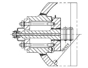
To address these issues, a design optimization incorporates a self-tightening seal [4] for the manhole structure. In this improved configuration, the manhole cover is positioned inside the equipment, and bolts only need an initial pre-tightening force to establish the initial seal. As the internal pressure rises, the manhole cover experiences increased internal pressure, leading to a tighter compression of the sealing gasket. The higher the internal pressure, the more effective the sealing force exerted by the manhole cover. Refer to Figure 2 for a detailed illustration of this optimized structure.

Figure 2 Self-tightening manhole structure
When selecting a gasket for the manhole, high-pressure equipment typically employs octagonal or corrugated composite gaskets at the nozzle. To meet sealing requirements and leverage past experience, octagonal and corrugated composite pads are suitable choices. However, the challenge arises as the manhole cover is located inside the equipment, limiting the gasket installation to before the final circumferential seam of the cylinder is welded. Consequently, both the octagonal and corrugated composite gaskets cannot be replaced once installed, and the equipment's heat treatment may impact their sealing performance.
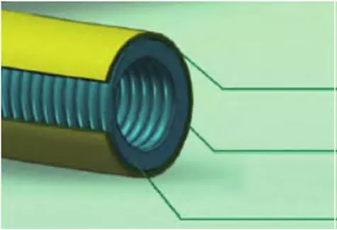
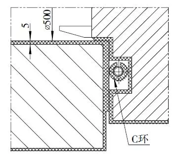
In consideration of facilitating gasket replacement for the manhole, an elliptical diameter gasket is contemplated. This type allows for replacement after opening the manhole, but its uneven sealing force poses challenges in accurate calculations, potentially leading to leaks over prolonged use. After thorough investigation, the final choice is the C-ring self-tightening sealing gasket. Illustrated in Figure 3 with a three-layer structure, its distinctive feature lies in its ability to undergo slight deformation. The C-ring can transform into an oval shape by applying a force in the radial direction of the annular cushion, facilitating installation through the manhole. Collaborative discussions with the C-ring manufacturer result in the confirmed seal groove structure depicted in Figure 4.

Fig. 3 C ring cross-section structure

Fig. 4 C ring seal groove structure
Design of hinge mechanism
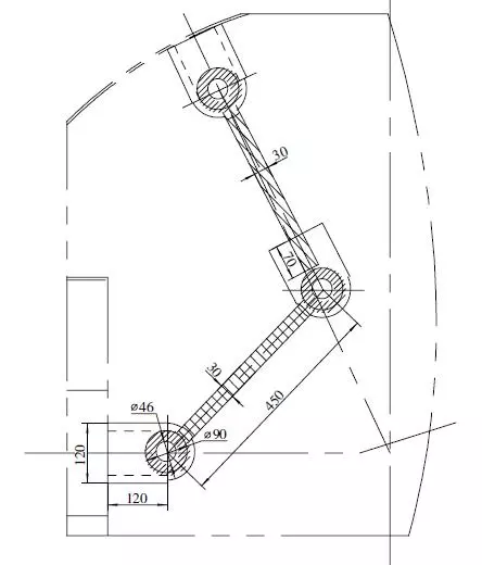
Within the equipment, an internal manhole cover features an air inlet. To ensure smooth opening, a horizontal-only hinge mechanism is installed. The opening process involves the air inlet connecting pipe moving inward along the equipment's axis until the flange completely enters the equipment's interior. Subsequently, the entire rotation of the hinge mechanism results in the complete opening of the manhole cover. Closing the manhole follows the reverse steps. The hinge mechanism, designed with three rotating shafts, guarantees a smooth operation during both the opening and closing phases.
Throughout the manhole's movement, maintaining horizontal motion is crucial, with no displacement permitted in the vertical direction. The hinge connecting rod must possess adequate strength and rigidity to balance the bending stress induced by gravity. Figure 5 illustrates the configuration of the hinge mechanism, highlighting its functionality in facilitating the horizontal and controlled opening and closing of the manhole.

Figure 5 Hinge mechanism
Form of welded joint of shell
All welded joints in the equipment must undergo complete penetration. Considering the equipment specifications, material characteristics, and welding conditions, a suitable welding joint form is determined to ensure welding quality. Given the high-pressure fatigue conditions, it is essential to polish the excess height of the welding seam to be flush with the base metal. The connections between the connecting pipe and the shell are butt joints. The thick wall of the shell employs a U-shaped groove for circumferential welding, while the connection between the connecting pipe and the shell utilizes a half U-shaped groove on the shell. This design reduces both welding material consumption and the workload during the welding process.
Finite element stress analysis and calculation
As the equipment's design pressure exceeds GB/T 150, coupled with pressure fluctuations and challenging operational conditions, a standard design approach is inadequate. Thus, it becomes imperative to conduct a comprehensive analysis and design using finite element analysis to assess strength and cumulative fatigue damage. Adherence to JB 4732 standards dictates the equipment's design, manufacturing, inspection, and acceptance processes.
The entire equipment undergoes modeling, analysis, and calculation, employing a full elastic material constitutive model. Elastic analysis yields the nominal stress of Tresca for the equipment. The linearization method evaluates the stress intensity at structural discontinuities, and the resulting alternating stress amplitude (Salt) is scrutinized for fatigue accumulation and total cumulative damage over the equipment's lifespan.
For the connection between the manhole cover and equipment, a Normal Lagrange nonlinear contact algorithm is applied. This includes setting a friction coefficient and checking the contact compressive stress. The Tresca stress contour plot for the equipment, derived from these analyses, is presented in Figure 6.

Fig. 6 stress nephogram of Tresca equipment
Manufacturing difficulties and technical requirements
Requirements of surface roughness
The equipment requires surfacing, processing, heat treatment, and polishing, with a stipulated roughness requirement of better than 0.25 μm[5]. Polishing encompasses various components, including the inner wall of the equipment, girth welds, fillet welds, and surfaces of other parts. The polishing process involves the use of an industrial tank polisher, a vertical lathe tool holder micro polisher, a Chiba wheel, and a wire drawing wheel. The welding and polishing plan is adopted for the shell using electrodes. The inner wall of the connecting pipe undergoes polishing with a rolling knife, while the manhole surface is polished using a micro-polisher in conjunction with a vertical lathe. The shaft surface is polished using a micro-polisher and a horizontal lathe. Following the polishing phase, the effectiveness is assessed by polishing a reference block and utilizing a roughness detector.
Welding requirements
To prevent deformation during pipe installation, the left head features a sizable opening at its center, accompanied by internal and external anti-deformation supports. The nozzle undergoes initial welding with an allowance, followed by post-welding processes, including heat treatment and precision sizing of the sealing surface based on the head port. Butt joints are employed for the inlet flange and manhole cover, with careful consideration for welding amounts to minimize deformation. Symmetrical and even tying of the inlet nozzle flange and manhole cover precedes a two-stage welding process, with annealing halfway through to relieve stress. The cylinder surfacing is machined, ensuring a minimum 8mm thickness by increasing the surfacing layer to 6mm. Automatic welding of circumferential seams between cylinder joints and the left head ensures quality and facilitates subsequent polishing.
Requirements for Dew Point Test
The equipment is tasked with conducting a -80℃ nitrogen dew point test, showcasing its capability to handle this specific test temperature. The objective is to identify and address factors influencing the dew point test systematically. The -80℃ dew point test on the liquid nitrogen source is crucial for verifying the medium's ability to reach the specified dew point of -80℃, correlating to a water vapor content of 0.54×10^6 per standard. Given the equipment's substantial internal volume, a rapid and effective method to reduce water content is essential to ensure successful realization of the -80℃ dew point test. Ultimately, the equipment undergoes a step-by-step replacement process to accomplish the dew point test.
Concluding remarks
The gas storage tank is subjected to high pressure and fatigue loads, accompanied by specific user requirements. It is imperative to grasp the key aspects of structural design, addressing manufacturing challenges to ensure a rational design and accurate production. The design process prioritizes considerations for fatigue loads, implementing a self-tightening sealing structure with a C-ring sealing element that allows slight deformation. During manufacturing, meticulous control of welding and heat treatment deformation, coupled with interior polishing and nitrogen replacement, ensures the ultimate product quality. This innovative product addresses several gaps in Lanshi Company's self-sealing structure design and manufacturing, significantly boosting competitiveness in the market. It has successfully penetrated the military market, meeting anticipated technical benchmarks and achieving positive market impact.

